|
|
|
 | Telescope |
|
|
|
| |
The SPT will be a 10-m off-axis Gregorian telescope on an alt-az mount. The general arrangement is shown in Figure 1. The telescope design is driven by the demanding science goals which require high sensitivity measurements of low contrast differential emission over a broad survey region. A large instantaneous field of view, low system noise, and stringent control of systematic offsets such as differential pickup of thermal ground emission are essential.
|
| |
 Figure 1. (Left) rear view of the SPT at elevation 0o, and (right) side view at elevation 45o with the outer ground shield.
|
| |
The telescope has key features designed to meet these needs:
- High throughput. The SPT has a ~ 1 deg2 diffraction-limited field of view at λ = 2 mm, so it can support cameras with several thousand detectors.
- Low noise. The off-axis design gives low scattering, the gaps between primary panels are sealed, and the beam is well shielded. There are shields around the beam along the secondary support structure, and the entire telescope sits inside a large, stationary, conical ground shield. The primary is equipped with de-icing heaters to prevent ice from accumulating on the panels. All these lead to low optical loading on the detectors, in turn leading to high sensitivity.
- Low offsets. The entire telescope can be chopped and scanned, so the beam does not move on the telescope mirrors. The drive supports 2os-1 slew rate in elevation, 4os-1 in azimuth, 4os-2 acceleration in both axes, and position switching over 1o in 1.5s (settling within 3 arcseconds of the required position). In addition, the extensive ground shielding leads to low sidelobe response in the direction of local features (eg buildings, and the horizon).
- Submillimeter operation. The primary has a surface accuracy of 20 µm rms, and the pointing accuracy of the telescope is 1.5 arcseconds rms, so operation at wavelengths as short as 200 µm will be possible.
|
| |
The telescope is being built by VertexRSI. It will be assembled and tested in the US in Jan - May 2006, prior to deployment at the South Pole in Nov 2006 - Jan 2007. |
| |
Optical Design
We have chosen a classical Gregorian design for the SPT to provide flexibility for future optical configurations. In particular this design can accommodate a chopping mirror at the pupil after the secondary, and in the classical Gregorian design (with a paraboloidal primary) the focal ratio of the telescope can be changed simply by replacing the secondary. The off-axis form was chosen because it allows a large secondary, and hence a high throughput, with low scattering and high efficiency.
Millimeter-wave Gregorian telescope designs typically have a chopper at the pupil just after the secondary. This arrangement requires re-imaging optics for low aberrations over a wide-field of view. Unfortunately, the many reflections in these designs lead to degraded sensitivity (~ 1% loss per warm mirror, causing extra loading on the detectors), high instrumental polarization, and chop-synchronous offsets (due to the beam moving on the secondary). Since the SPT is capable of fast scanning, we have adopted a much simpler optics configuration in which the camera is located at the Gregorian focus and there is no chopping mirror. In this compact two-mirror scheme, the stop is at the secondary (as in a typical infrared telescope) and spillover on the stop is absorbed by a cold load which surrounds the beam between the camera and the secondary.
The optical configuration of the SPT, and corresponding spot diagrams, are shown in Figure 2 and Figure 3. The Gregorian focus is very fast (f/1.3), which gives maximum coupling to feedhorns of diameter 2fλ = 5 mm at λ = 2 mm. In this case, a 1000-element bolometer array is ~ 150 mm in diameter. The secondary is only 1 m in diameter, which is important because: (i) it sets the size of the cryostat for the cold stop; and (ii) the difficulty and cost of making a monolithic secondary increases rapidly with diameter if the secondary is larger than ~ 1 m. The Gregorian focus is stigmatic at the field center, and the geometric cross polarization is zero, i.e., the system satisfies the Dragone condition. At a field radius of 0.5 o the peak cross-polar response is roughly -30 dB.
|
| |
 Figure 2. Optical configuration of the SPT. Solid lines are the principal and marginal rays for the field center. Dashed and dot-dashed lines are for the edges of a 1o diameter field.
|
| |
 Figure 3. Spot diagrams. Circles show the Airy disc at λ = 2 mm.
|
| |
The secondary and the entire beam path from prime focus to the camera is cooled, giving low noise and stable spillover. The loss of the telescope is also low because there is just one warm reflection (at the primary) and one warm transmission (through the cryostat window near prime focus). The penalty for placing the stop at the secondary is ~ 10% degradation in resolution because the illumination pattern on the primary varies with field position. The entrance pupil of the SPT is 56 m in front of the primary, so the illumination pattern at the edge of a 1o diameter field is displaced ~ 0.5 m. Thus, the diameter of the illumination pattern must be ~ 1 m smaller than if the entrance pupil were at the primary.
Roughly 25% of the power from a 2fλ diameter, smooth-wall, conical feedhorn spills over the secondary and falls on the cold stop, so emission from the stop can cause significant loading. The temperature of the cold stop in the SPT is ~ 10K, which gives a reasonable compromise between sensitivity loss (~ 5% at the zenith at λ = 2 mm) and the difficulty of cooling a large mirror assembly. As shown in Figure 4, the cold stop is a conical absorbing shroud, with annular baffles near the Gregorian focus. The secondary is a lightweighted mirror (total mass ~15 kg), machined from an aluminum plate, with thermal cycling between machining steps to reduce deformation of the finished mirror on cooling. The secondary and stop assembly is supported by a truss attached to the cryostat wall near the prime focus port. Since the SPT must support cameras for different wavelengths, and also a polarimeter, the cryostat is split into two parts, one containing the secondary and cold stop, the other containing the detector array. The two cryostats share the same vacuum, but have independent refrigerators.
|
| |
 Figure 4. A cutaway view of the cold secondary and 10K baffle optical configuration. Radiation from the primary enters through a foam vacuum window from the upper left, passing through an IR blocking filter that reduces radiative heat input on the 10 K system. The baffle is formed by two metal cones coated with a millimeter-wave absorber, with black annular rings attached to the cone wall near the 4K lens and focal plane. For a Gaussian beam with 6 dB edge taper and a baffle emissivity of 0.5, ray-tracing of this design shows that less than 1% of the spillover power eventually exits the cryostat window.
|
| |
A lens immediately in front of the detector array makes the focus telecentric to improve coupling to the feedhorns. This lens is quite weak (~ f/10), so it can be made from a material with fairly low refractive index, e.g., high-density polyethylene. A silicon lens would give lower loss, but a suitable anti-reflection (AR) coating is not yet available. A wideband AR coating for the plastic lens is also not entirely straightforward. We are considering machined, profiled grooves and a multi-layer stepped-index coating made of thin sheets of laser-drilled plastic.
A key advantage of the SPT observing strategy is that the entire telescope is scanned, so the beam does not move relative to the telescope mirrors. This approach reduces offsets, but in practice there will be some scan-induced deflections and associated changes in spillover. The stability of the beam on the window and heat blocking filter near prime focus is a particular concern because the beam there has fairly sharp edges. For a filter over-sized by 10 mm in radius, a displacement of the filter changes the power at the detector by ~ 30 mK mm-1. The receiver noise is ~ 100 µK Hz-1/2, so scan-asynchronous changes of more than a few micrometers in the position of the beam on timescales corresponding to the signal band will degrade the sensitivity. Temperature fluctuations in the cold stop also add noise, but typically will not be synchronous with the telescope scan. Again to avoid degrading sensitivity, such fluctuations much be below the level of a few x10 µK Hz-1/2 averaged over the detector readout bandwidth.
|
| |
Primary
The 10-m f/0.7 SPT primary design has lightweighted machined aluminum panels (each roughly 0.75x0.5 m), mounted on a carbon fiber reinforced plastic (CFRP) back-up structure (BUS). The panels will have ~ 8 µm rms surface accuracy. Differential contraction between the BUS and panels makes the panel gaps wider at lower ambient temperatures; if unaddressed, the effect of these gaps (emission and scattering) would increase as the atmosphere improves. At the South Pole, the temperature of the primary could be as high as -10oC in summer, and to prevent the panels from touching at this temperature the panel gaps must be ~ 2 mm at -80oC. Emission from the gaps, and offsets due to small movements of the beam relative to the gaps, are a serious concern, so we plan to cover the gaps with ~ 0.1 mm thick metal strips held in place by spring fingers.
Ice on the primary panels increases the telescope emission, and causes slowly-varying offsets, and ice in the panel gaps can change the alignment of the panels. Some telescopes at the South Pole have employed manual de-icing techniques, but these are impractical for a 10-m telescope. The SPT primary will be equipped with de-icing heaters, e.g., heat blankets on the BUS, or hot air blowing between the BUS and the panels. In addition, we will select a panel surface finish that discourages ice accumulation. We are currently testing a variety of finishes at the South Pole, e.g., polished, etched, anodized, and SiO2 coated. Initial results from this test indicate that ~ 50 Wm-2K-1 is required to heat the panels, a few K temperature rise is enough to de-ice the panels on timescales of a day or two, and the different surface finishes have roughly similar icing characteristics (but the coated surfaces are generally colder than the bare aluminum surfaces). Since de-icing can be done with a very small temperature increase, we are currently planning to run the de-icing heaters continuously at low power. This avoids the problem of having to wait for the primary to recover its profile after high-power de-icing, and reduces the peak demand on the South Pole power plant.
The SPT primary has 217 panels, each with 4 axial and 3 in-plane adjusters. The surface will be aligned initially to ~ 60 µm rms based on photogrammetry measurements, and later to 20 µm rms based on holography. Setting all the panel adjusters under the conditions at the South Pole will be a difficult task, so access to the adjusters is from inside the BUS. This is a cramped environment, but it provides protection from the wind, and allows access to the adjusters without a crane or man lift.
|
| |
Ground Shields
Low noise is a critical requirement for the SPT, so the design includes several levels of shielding. The inner shield is a trough running along the secondary support as shown in Figure 1. Gaps between the inner shield, primary and secondary support are sealed with reflecting material, and the top edges of the shield and primary are rolled with a radius of a few cm to reduce scattering. The inner shield does not have de-icing heaters, so it will require occasional brushing to remove snow (through doors at the bottom of the shield near the primary).
The outer shield is an enormous inverted cone around the entire telescope. The wall angle of the cone is shallow enough to prevent radiation being trapped between the shield and the (reflective) back of the primary, so the shield does not require a floor. This makes snow removal much easier. The shield is made of 1.25-mm thick aluminum panels ~ 3 m across (the width of an LC130 aircraft) supported by a steel spaceframe. The panels are finished with a smooth epoxy phenolic coating to encourage snow shedding. A 60o wide section of the shield can be lowered to allow short, occasional observations near the horizon, e.g., calibration observations of planets, and holography using a test source on a tower. Ray tracing of the telescope with inner and outer shields shows that variations in ground pickup will be < 1mK per degree change in elevation.
|
| |
Mechanical design
The SPT primary and secondary are mounted on a massive L-shaped frame on an alt-az fork mount (see Figure 1). The mount is made entirely of steel, and the CRFP BUS is attached to the steel L-frame via an Invar cone. The mount is balanced about both axes to minimize deflections in the structure and settling of the foundation, but this requires a large elevation counterweight. The azimuth bearing is at the top of a conical pedestal, which is supported by a massive spaceframe sitting on wood footings. The base of the pedestal is ~ 4 m above the ice to reduce snow drifting around the structure. Table 1 shows the masses of the major components of the SPT. Each component is designed so that it can be broken down into parts that will fit in an LC130 aircraft (which can carry about 11 metric tons).
Table 1. Expected masses of SPT components.
Component | Mass (metric tons) |
Foundation frame + footing | 34 |
Pedestal | 23 |
Fork | 16 |
L-frame | 77 |
Counterweight (lead) | 73 |
Primary (Invar cone + BUS + panels) | 18 |
Secondary + camera | 3 |
Total | 244 |
|
| |
Each axis has two pairs of torque-biased motors. The azimuth motors drive a ring gear inside the azimuth bearing, and the elevation motors drive sector gears on each side of the L-arm. The yoke and L-frame contain CFRP reference structures with displacement sensors to measure gravitational and thermal deflections of the mount. An active optical bench, which is coupled to the reference frame system, supports the secondary and camera. In this configuration, the relative positions of the secondary, lens and detector array are fixed and the entire assembly is continuously adjusted (with a control bandwidth of ~ 0.1 Hz) to maintain its position with respect to the primary. The mount also has tiltmeters above and below the azimuth bearing to measure changes in the tilt of the structure (which are included in the pointing model with a bandwidth of ~ 0.1 Hz). All the SPT drive components are modular, moving parts and critical electronics are in warm environments, and the drive motors, gearboxes, encoders, reference frame sensors and tiltmeters can be reached from the control room without going outside. The outside of the mount is insulated to reduce differential cooling, and interior spaces in the pedestal and fork are warmed by air from the control room.
The receiver cabin is a large (~ 6m long x 3m high x 2.5m wide) shielded and insulated room at the end of the L-frame. This provides a laboratory environment for optics and cameras, with enough space to accommodate future optical configurations with many mirrors and several optical benches. A door in the floor of the cabin mates with a hatch in the control room roof when the telescope is at the horizon (see Figure 1). Access to the cabin is also possible from outside, through the L-frame, in any telescope position.
|
| |
| Receiver |
|
|
|
| |
The statistical arrival of photons presents a fundamental limitation to the sensitivity of bolometric detectors, which has been reached for small ground-based arrays of detectors operating at mm-wavelengths. The SPT science objectives require significant advances in mapping speed; to achieve this, the SPT receiver will be based on a focal plane with 1000 superconducting Transition Edge Sensor (TES) bolometers. Observations will be done simultaneously in at least three frequency bands to enable spectral separation of various celestial sources. Reading out 1000 cryogenic detectors poses a technological challenge; we plan to use a SQUID-based frequency domain multiplexer readout to minimize the complexity and heat load of cold wiring. To minimize maintenance and cost of operation, the bolometer camera will be cooled by the combination of a 250mK closed cycle refrigerator and a mechanical refrigerator that reaches 2.3K without liquid cryogens. In the following sections we describe the detector array, cryogenics, readout technology and cryostat optics.
|
| |
Focal Plane Array
The SPT focal-plane array will use horn-coupled spider-web bolometers with superconducting Transition-Edge Sensors (TES). Compared with conventional semiconductor-based technologies, TES detectors offer several advantages for the construction of large arrays. First, the bolometers are produced entirely by thin-film deposition and optical lithography, greatly simplifying fabrication and improving the uniformity of devices. Second, readout multiplexing technologies have been developed for TES detectors that have the potential to greatly reduce the complexity and cost of large arrays. Other benefits include high linearity and well controlled responsively independent of base temperature and optical-loading, due to the TES's strong electrothermal feedback effect. In addition, voltage biased TES bolometers are also quite insensitive to vibration by virtue of their low impedance.
The SPT array will be assembled from 6 pie-shaped wedges each with approximately 160 bolometric detectors. Each detector consists of a small Al/Ti bi-layer TES suspended on a gold-covered Silicon Nitride spider-web absorber. We have fabricated 55 element prototype wedges of TES detectors on 4 inch wafers with high yield, like those shown in Figure 5 and Figure 6. The individual detectors in the 55 element wedges meet the requirements for the SPT array, though the 160 element SPT wedges will need to be built on 6 inch diameter wafers.
|
| |
 Figure 5. Montage image of a single 55-element TES spider bolometer wedge to show how an array of six identical wedges would look. The complete prototype array will have 330 bolometers and be 12 cm in diameter.
|
| |
 Figure 6. Close up of a 55 element bolometer wedge. The sensors are constructed with an Al/Ti proximity effect sandwich. Webs are metalized with gold for microwave absorption. Suspended spider-web absorbers are fabricated from 1 µm thick silicon nitride. The membrane is released from the front side using a gaseous xenon diflouride etch. Bolometers are 5 mm diameter with 0.5 mm long legs. Wiring layer is superconducting aluminum. This array was fabricated in the U.C. Berkeley microfabrication facility.
|
| |
The sensor is a bi-layer of Aluminum and Titanium, with layer thicknesses tailored to give a transition temperature of 0.5K. In order for the detectors to operate with strong electrothermal feedback, the thermal conductivity needs to be chosen such that when they are subjected to the maximum expected optical load, the electrical power applied to keep the sensor in the transition region is comparable to the optical power. Unfortunately the optical background can be hard to predict and depends on the frequency band and elevation of the observations. From experience with ACBAR, we estimate the emission from cryostat optics, filters, vacuum window, and the warm primary mirror (taken to be 1% emissive) will be approximately 20K in all frequency bands. We conservatively set the thermal conductivities G to values appropriate for 3-5 times more electrical power than the expected total optical loading during observations at elevation 60o. Even with this conservative design, the photon noise completely dominates the total noise of the detectors. Compared with NTD bolometers, the TES detectors have a much smaller contribution from Johnson noise in the sensor, and therefore somewhat lower total noise. In the 2.1mm band, the array will image one square degree of sky to an RMS of ΔTcmb ~ 10µK in a single hour of observation.
|
| |
Cryogenics
The baseline for the SPT receiver is to use a system free of expendable cryogens, which has strong benefits for operations at the South Pole. We have assembled a test system using a Cryomech model PT-405 pulse tube cooler which provides 0.7W of cooling power at 4.2K and a base temperature of 2.3K. A Chase Research 3-stage Helium sorption refrigerator operates from the pulse tube cold stage. It has one stage of 4He used to condense 3He in two separate reservoirs, the warmer of which acts as a buffer for the coldest stage. The entire sorption refrigerator cycling process takes about 2 hours; the cold stage then maintains a steady temperature of 250mK for 56 hours under an external heat load of 1µW. The buffer 3He stage operates at 350mK with a cooling power of 100µW; this stage is used to intercept heat loads from wiring and mechanical supports. We have found that vibrations from the pulse-tube cooler do not excite a substantial microphonic response in the TES bolometers, and we can achieve the baseline detector noise with the pulse-tube operating.
We have also made detailed measurements of the temperature fluctuations on each of the cryogenic stages. The fluctuations at 250mK and 50K are small enough to be negligible in the total detector noise budget. However, at 3K the fluctuations from the cycling of the pulse tube can be as large as 50mK. It will be necessary to control the temperature of the 3K lens and IR blocking filter to a level of approximately 1mK so that this signal is below the noise floor of the detectors. This will be achieved with a passive thermal circuit that makes use of a weak link to the large heat capacity of the cold lens. A gas gap heat switch will be used to speed the initial cooling of the lens and filter assembly from 300K.
|
| |
Receiver Optics
Due to the wide field of view of the SPT, the receiver optical elements are quite large and present considerable fabrication challenges. In Figure 4, we show a concept drawing of the cold optics box and receiver. An array of smooth wall conical feeds is used to couple the incoming radiation to the detector array. The secondary acts as a cold stop and truncates the side lobes produced by the conical feeds. Figure 7 shows a prototype 55 element conical horn array, fabricated from solid Aluminum with a set of custom ground reamers and then gold plated. The technology used to produce this prototype is easily scalable to the 160 element wedges planned for the SPT.
|
| |
 Figure 7.
A 55 element horn array mounted on top of a prototype detector wedge. The SPT array will have approximately 160 horns and detectors per wedge.
Figure 7.
A 55 element horn array mounted on top of a prototype detector wedge. The SPT array will have approximately 160 horns and detectors per wedge.
|
| |
A relatively low-power lens is used to convert the incoming beam to the appropriate f-1.3 feed for the horns. This lens will be fabricated from polyethylene with an anti-reflection (AR) coating. The IR blocking and lowpass band-edge defining filters are constructed by bonding conductive mesh layers on polyethylene films in a heated press. The SPT optics require filters between 200-250mm in diameter, the size of which presents a serious challenge but is within the capabilities of the fabrication facilities at Cardiff. The lower edges of the frequency bands are set by the cutoff frequency of a small section of circular waveguide behind the conical horns. The conical horn array, filters and possibly the AR-coated lens will need to be changed in order to change observation bands. We are planning to make these systems as modular as possible to facilitate rapid band changes.
As can be seen in Figure 4, the cold optics design incorporates a relatively large vacuum window. We have recently built and tested a 12'' diameter window appropriate for use with the SPT. The window is constructed from a 3'' thick laminate of Zotefoam PPA-30 nitrogen expanded polypropylene. It appears to be mechanically robust and holds an excellent vacuum. The total loss through the window has been measured to be less than 1.0% at 150 GHz.
|
| |
Frequency Multiplexed SQUID Readout
One key to implementing an array of more than several hundred bolometers is readout multiplexing, which can dramatically reduce the heat load, the complexity of cryogenic wiring, and the cost. The SPT utilizes a frequency-domain multiplexer which requires only a single SQUID to read out a module of several bolometers. The number of bolometers per readout module is still uncertain; eight has been demonstrated and 32 appears to be practical, so each wedge of the array will require several readout modules.
A schematic diagram showing the basic components of the readout system is shown in Figure 8. The bolometers are sine-wave biased with a constant voltage amplitude carrier, in the frequency range of 500 kHz to 1 MHz. Each bolometer within a readout module is biased at a different frequency. The sky-signal changes the bolometer resistance and amplitude modulates the bolometer current such that the signal from each bolometer is transferred to sidebands adjacent to its carrier. Thus, the signals from different bolometers within a module are uniquely positioned in frequency, so they can be summed and connected through a single wire to a SQUID amplifier.
|
| |
 Figure 8. Schematic diagram showing the basic components of the frequency multiplexed SQUID readout system.
|
| |
Each bolometer is part of a series-resonant LC circuit, which is tuned to the appropriate bias frequency. This allows the bias frequencies for all bolometers in a module to be applied through a single wire, as the tuned circuit selects the appropriate frequency for each bolometer. Thus only two wires are needed to connect the bolometers of a readout module on the 0.25K stage to the 4K stage on which the SQUIDs are mounted. The tuned circuits also limit the bandwidth of the bolometer's Johnson noise, which would otherwise contribute to the noise in all other channels of the module. The comb of amplitude modulated carriers at the SQUID output is transmitted to a bank of demodulators that mix the signals back down to base-band. The signals are then filtered and digitized, and all outputs in the array are sampled synchronously. Multiplexing of 8 channels has been demonstrated and the limit to the number of channels per readout module is being explored. The high-Q superconducting LC filters use lithographed inductors and commercial NP0 ceramic chip capacitors. All inductors have the same value, so the Q increases with frequency to maintain constant bandwidth. A 16 µH inductor together with the bolometer resistance determines the bandwidth (5 kHz), and the capacitor sets the frequency of each channel. Both the inductors and chip capacitors are compact and together occupy an area comparable to a single pixel in the array. The filters will be mounted on a board underneath the bolometer array.
The SQUID parameters must be chosen carefully to achieve the required noise performance and dynamic range. It is necessary to use SQUID devices with a small input coil to accommodate large amplitude carriers and reduce susceptibility to spurious pickup that degrades SQUID performance. This necessitates a large transimpedance of the SQUID amplifier to override the noise of the warm electronics. To meet these requirements, we utilize 100-element series array SQUID amplifiers supplied by NIST. The SQUIDs are packaged on pc-boards in groups of 8 as shown in Figure 9. SQUIDs are extremely sensitive to magnetic fields and must be shielded very carefully; each board is enclosed in a cryoperm shield as shown in Figure 10. In addition, each SQUID array is individually mounted on a thin niobium film to pin the residua magnetic field. The attenuation achieved with this cryoperm/Nb shielding is better than a part-per-million at the frequencies of interest.
|
| |
 Figure 9. A printed circuit board with eight 100-element squid arrays mounted individually on top of Niobium pads. The board is mounted inside the Cryoperm shield and the Niobium films pin residual magnetic fields.
|
| |
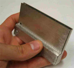
 Figure 10. A prototype cryoperm shield is shown. The shield attenuates magnetic fields and provides mechanical support for the pc-board mounted SQUIDs.
|
| |
Maintaining constant voltage bias for the bolometers necessitates that all impedances between the bolometer and the bias resistor are much smaller than the bolometer resistance. Thus, the SQUID amplifier is operated with shunt feedback to obtain a low input impedance, while linearizing the SQUID response and extending the signal range to accommodate the high level bias carrier signals. The required gain-bandwidth product of the feedback loop requires short connections,so the SQUID controller is mounted directly on the side of the receiver cryostat. The noise of the readout system is less than 10 pA/(Hz)1/2 and lies well below the noise floor of the detectors planned for SPT. The system has the large dynamic range and bandwidth (1 MHz) required for frequency domain multiplexing. The SQUID controller and demodulator are computer controlled with extensive monitoring and diagnostic capabilities.
The amplified comb of carriers are passed from the SQUID controller to the oscillator/demodulator boards shown in Figure 11. Each board combines 16 demodulator channels. Since one demodulator channel is used for each bolometer, about 60 boards are required for SPT. Three 9U VME crates accommodate the readout, which is mounted in a separate rack near the cryostat. The high frequency bias carriers are generated by Direct Digital Synthesizers (DDS), which provide precise frequency and amplitude control with very low sideband noise. The same DDS that generates the bolometer bias also provides the local oscillator signal for the corresponding demodulator. The demodulator circuit utilizes a sampling demodulator with very high dynamic range followed by an 8 pole low-pass anti-aliasing filter, and a 14 bit analog-todigital converter. A field programmable gate array assembles the data from all channels on a given board and streams it to the data acquisition computer. Final testing of the oscillator/demodulator production prototypes is underway.
|
| |
 Figure 11.
The 16-channel oscillator/demodulator boards provide the AC bias sine-wave carriers which are sent to the bolometers. The carriers with associated sky-signal amplitude modulation are received from the bolometers and SQUID amplifiers, mixed down to base band, and digitized on-board. One oscillator/ demodulator channel is required per bolometer, therefore, 60 boards in three 9U VME crates are needed for the SPT receiver.
Figure 11.
The 16-channel oscillator/demodulator boards provide the AC bias sine-wave carriers which are sent to the bolometers. The carriers with associated sky-signal amplitude modulation are received from the bolometers and SQUID amplifiers, mixed down to base band, and digitized on-board. One oscillator/ demodulator channel is required per bolometer, therefore, 60 boards in three 9U VME crates are needed for the SPT receiver.
|
| |
|
|
|